
How to continue design when there's no power
There are a few challenges so common they become rites-of-passage for EMI project trips. A vehicle breakdown. At least one team member with digestive issues. And the puzzle of building the network of power cables and adapters needed at the team “base camp”. Often, our ministry clients are working in parts of the world where electric power is scarce. Even many of the EMI field offices face the regular prospect of power outages, as utility companies struggle to keep up with rapidly rising electric demand. (As I write this article, the power has come and gone 5 times). And sometimes, electricity becomes unavailable at a very inopportune moment.
Decades ago, all engineering was done without the benefit of electronic calculators or computers. However, taking our engineering methods back in time isn’t that simple. Our designs have become more complex and ambitious. Our methods, taking advantage of the tools at our disposal, have become more refined. And quite honestly, the skill sets of most engineers have changed.
As structural engineers in a digital age, how can we be prepared to maximize our effectiveness when the lights go out?
This EMI Tech article will focus on the challenges faced during a ‘typical’ EMI project trip. As such, many of these simplifications will have limitations that won’t apply universally. We’ll focus on typical EMI structures in the developing world: low-rise reinforced concrete buildings with infill or confined masonry walls. And we’ll focus on the objectives that most commonly need to be met in the project trip timeframe: approximate column and beam sizes and spacings to guide the architectural concept.
Observation of Local Practices
Observing local construction practices can pay huge dividends in developing a culturally appropriate and constructible project. In addition to observing materials, spans and structural systems in use, keep an eye on some smaller details. Stairwells can sometimes give a window to observe floor slab styles and material thicknesses. Are columns and beams usually formed to be the same width, or is one typically wider? How are cantilever edges supported? Can you observe signs of grade beams, tie beams, or strip footings at ground level?
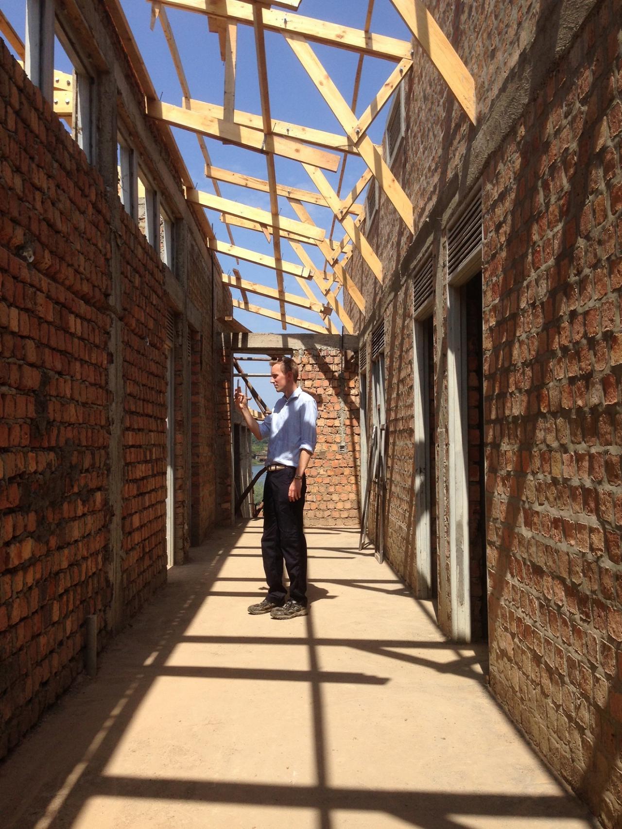
The grand prize on any project trip is to find a nearby building under construction, before the details are hidden behind facades and tile.
Observation is not without its weaknesses. While a building may have stood successfully for years, that alone is not necessarily enough to approve the design. Some elements will not be visible (e.g. most concrete reinforcing), there may be an unknown retrofit or repair history, materials and workmanship may have changed, or site conditions may not apply. Previous construction also may not meet the local codes and requirements currently in effect. As such, use observation as an initial guide, and then back up your observations with engineering principles.
Although details like the type of suspended slab system (in multistory construction) or infill walls are often not a major consideration to the architects, standard practices in the region will often impact building frame elements. Will floor slabs induce significant torsion in perimeter beams? Or can torsional cracking and redistribution of moments be allowed? Will “non-participating” infill walls be detailed to accommodate drifts? Or will they accumulate additional shears in your columns?
Analysis
Finite element analysis methods are a fantastic tool for structural engineers. They allow us to push the limits of structural design, and when used properly, determine a much more precise distribution of forces in indeterminate buildings. However, if your computer is out of power, or unable to access a network license server, what other tools can be used to for reasonably accurate structural analysis?
The first tool in any structural engineer’s toolbox should be published solutions for beams in various support and loading configurations. These are essential even with access to computer analysis, as a reference for verifying results. Through careful use of superposition and adjustments for realistic support conditions (e.g. not purely fixed or pinned), many structural elements can be designed relatively quickly by hand. For the ambitious, fixed-end moments from beam tables are also a starting point for some of the more complex hand analysis methods.
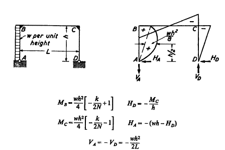
The next level of complexity is to consider the effects of frame systems. Solutions for single-bay frames under a variety of support and loading conditions have also been published; and can be combined through superposition to account for the relative stiffness of beams and columns. Although they are more difficult to combine for multi-story or multi-bay configurations under lateral loading, single-bay solutions can be a useful starting point for the effects of vertical loads on buildings of most configurations.
For multi-bay moment frames under lateral loading, the portal frame method is often applicable, and simple to solve. Assuming inflection points (usually at the mid-length of beams and columns) and base shear distributions reduces the indeterminate structure to a set of easily solved free-body diagrams – and can either be solved at length, or skipping to only the most critical elements.

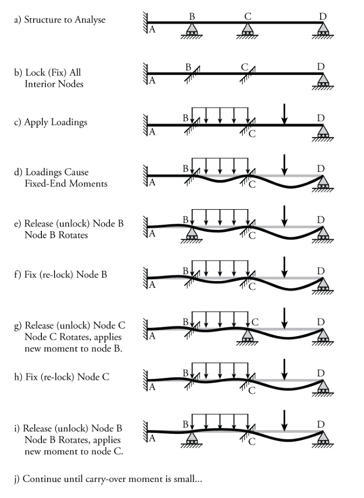
Finally, an ambitious engineer may take on the challenge of solving indeterminate structures by hand using a method like the Moment Distribution Method (aka MDM or “Hardy Cross”). Although requiring some iteration, and much simpler when prepared with a ready-built worksheet or spreadsheet, the MDM is a robust solution method that can be used in almost any situation to high levels of accuracy.
Reinforced Concrete Beams
When sizing beams, a few rules of thumb can significantly speed up your estimates.
One starting point for beam depth is the span limits for deflection, such as those found in ACI 9.5.2.1. As mentioned previously, beam width may be a function of the standard forming practice in the area. In Cambodia, it is common to see beams the same width as the column, or sometimes narrower, but only rarely wider (counter to common practice in many countries).
Thickness for Concrete Beams and One-Way Slabs (Kamara 2011)
|
Beams and One-way Slabs |
Minimum h |
|---|---|
|
Simple Span Beams or Joists* |
Ln/16 |
|
Beam or Joists Continuous at one End |
Ln/18.5 |
|
Beam or Joists Continuous at both Ends |
Ln/21 |
|
Simple Span solid Slabs* |
Ln/20 |
|
Solid Slabs Continuous at one End |
Ln/24 |
|
Solid Slabs Continuous at both Ends |
Ln/28 |
Another rule of thumb to ensure a beam has adequate size for flexural load is to use the following equation:
240·Mu = bd2 [kN-m for Mu, cm for b and d]
20·Mu = bd2 [kip-ft for Mu, in for b and d]
where Mu is the moment demand, b is the beam width, and d is the depth of reinforcement from the compression face.
In the lightly reinforced members common in the developing world (because of the relative cost of steel vs. concrete) beam dimensions as large as 400-500·Mu might prove most economical.
In another rule of thumb familiar to many experienced engineers, the area of reinforcing required can be estimated as:
As = 3·Mu/d [kN-m / cm]
As=Mu/(4·d) [kip-ft / in]
**Note: the rules of thumb above assume 28MPa (4ksi) concrete and 420MPa (60ksi) steel.
Columns
Many EMI projects utilize long and narrow building shapes, which allow for single loading corridors and increased energy efficiency through passive design elements, taking advantage of sun angles and prevailing winds. These building configurations can simultaneously raise challenges for the structural system. Moment frames with only one or two bays in the short direction will place high demands on columns in bending. In fact, many low-rise moment frame systems will see column sizes and reinforcing driven by flexural capacity (the very bottom edge of the P-M interaction diagram). This is often the case to the point where column design is controlled by the load combination with minimum axial load (e.g. factored dead load coefficients less than 1.0). If this applies for your structure, it is often appropriate to approximate column capacity as a pure flexural member, which is much more easily done by hand.
One limiting factor for columns, particularly those around the building perimeter (or other locations where beams end) is the need to develop the beam bars for negative moment flexure. Beams are designed to develop their negative moment strength at the face of the column, which means that in most cases the bars need to be fully developed between that face and the cover concrete on the opposite side of the column. This is most often accomplished with a hooked bar (cog). Depending on the code philosophy, that hooked bar will have geometric requirements, and that geometry may require a minimum column width.
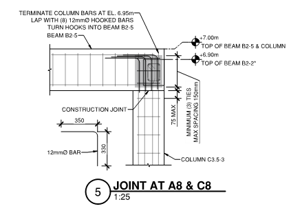
This can make for a useful tool to estimate column sizes early in a project. If the beam span and loads can be determined to make a reasonable estimate on beam bar sizes, this bar size can be converted to a hook development length. Adding the column cover distance and a few extra cm to allow for congestion and construction tolerances can establish a minimum column size threshold.

Especially in seismic regions of the world, other considerations that may govern column size may include “Strong Column Weak Beam” (SCWB) design, drift limitations, or joint shear considerations. SCWB provisions vary, but often call for column bending capacity 110% or 120% of the beam bending capacity at a given joint. Drift can be especially limiting for moment frames, which are among the softest of lateral force resisting systems. And joint shear will come into play in higher seismic design categories, particularly when concrete strengths are low. While multi-story drift can be difficult to calculate by hand, the other considerations can be approximated simply.
EMI Project trips often include surprises, so it’s best to be prepared. Being aware and familiar with the methods highlighted in this article can help a structural engineer provide helpful insight and design input even when the power goes out. For more information, check out EMI’s Structural Design Guide on our resource page.
Packing List
Here are a few resources that may be useful to bring in hard copy or on a low-power device like an e-reader or tablet to aid in hand calculations, if you find yourself without power during a project trip:
RC column P-M diagrams – found in many concrete design textbooks, or ACI SP-17 Vol. 3
Beam solutions – e.g the beam tables in AISC Manual, or NDS Design Aid No. 6
Portal frame solutions – e.g. Kleinlogel’s “Rigid Frame Formulas”
Moment Distribution Method worksheet or spreadsheet
The Simplified Design of Reinforced Concrete Buildings, PCA EB204
Bibliography
Erochko, Jeffrey. 2020. Learn About Structures. “Portal Method”.
Erochko, Jeffrey. 2020. Learn About Structures. “Moment Distribution Method”.
Your investment in EMI is a catalyst for change.
Community transformation starts with design. And design needs a strong foundation. Your donation to the EMI Fund supports everything we do.
EMI Tech is looking for contributors – write to editor@emiworld.org with your topic and article outline.