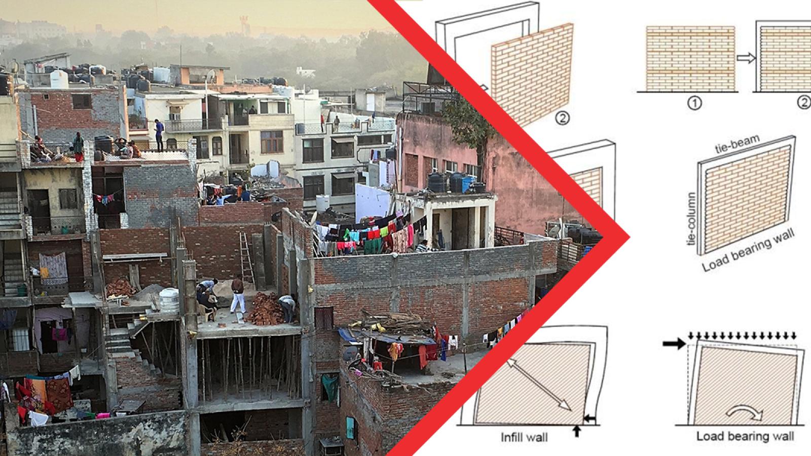
The differences between confined masonry and concrete frame with infill structural systems.
If you’ve spent time in a developing country (or even certain parts of the United States or Europe), you’ve probably seen them. Buildings with concrete columns and beams, laid out on a grid, with brick masonry or CMU forming the walls. This is perhaps the most prevalent construction type in the world. After all, concrete is readily available in most of the world; seen as more durable than wood or other lighter materials; and generally cheaper than steel. Coupled with the growing urbanization of the world’s population, this structural system is becoming the homes, schools and workplaces for a growing number of people. With the prevalence of this system, it is crucial we know how it’s built, how it responds to the outside environment and the design implications.
When it comes to construction, there are actually two different methods that are popular: the concrete frame with masonry infill method, and the confined masonry method. Although the end product may look similar, these two methods have drastically different means of transmitting both gravity and lateral loads.
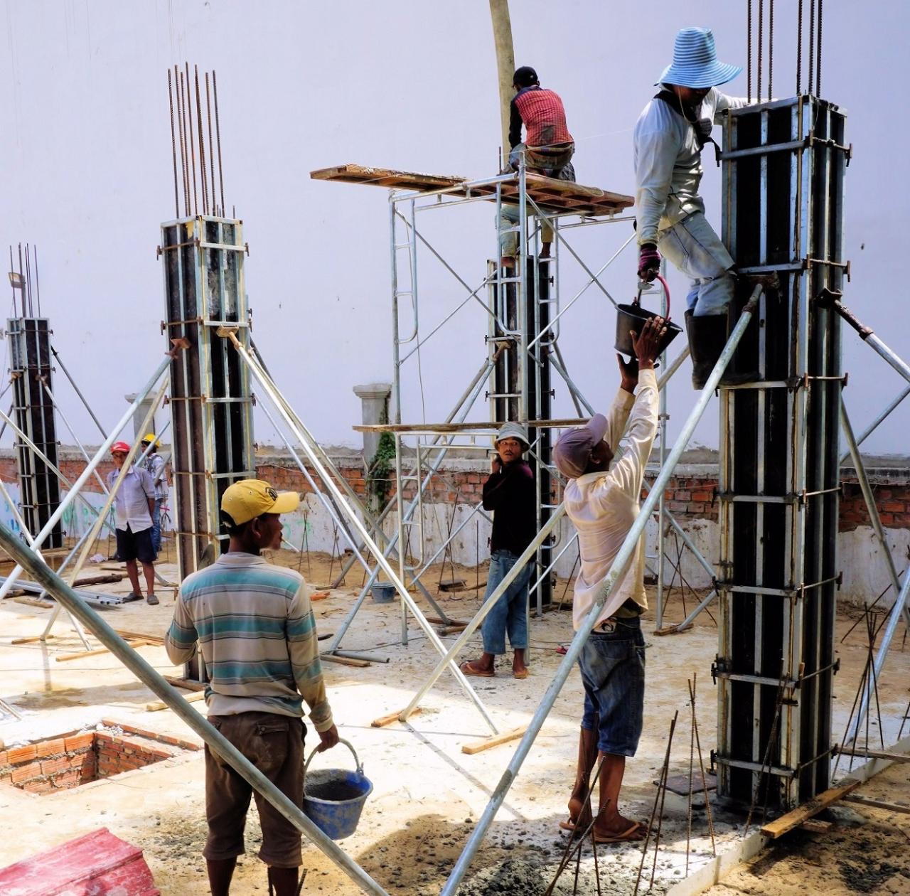
In the construction of concrete frame with masonry infill, the concrete frame is constructed first. Only later is masonry laid in between the columns and up to the bottom of the beam. When contractors erect the building in this manner, the concrete frame carries the gravity load. Often for lateral loads, the infill will interact with the frame, making it respond similar to a braced system. Despite the contribution that the infill provides, in many countries, the building is analyzed as if the infill didn’t exist, making it a concrete moment frame system. Generally, this approach will yield the flexural detailing required, but several additional aspects should be considered.
First is the location of the infill walls. Not all bays may have infill or large windows and doors may be present, greatly reducing the stiffness the masonry will provide to the system. Special care should be shown when laying out the infill so that the building doesn’t exhibit torsional irregularities. This is caused when the stiffness of one or two sides of the building are significantly less or more stiff than the others. Differences in stiffness from floor to floor can cause a “soft story.” Both of these circumstances greatly decreases the building’s ability to withstand lateral loads, especially when it comes to seismic loading. A regular layout of walls without openings should be present within the design.
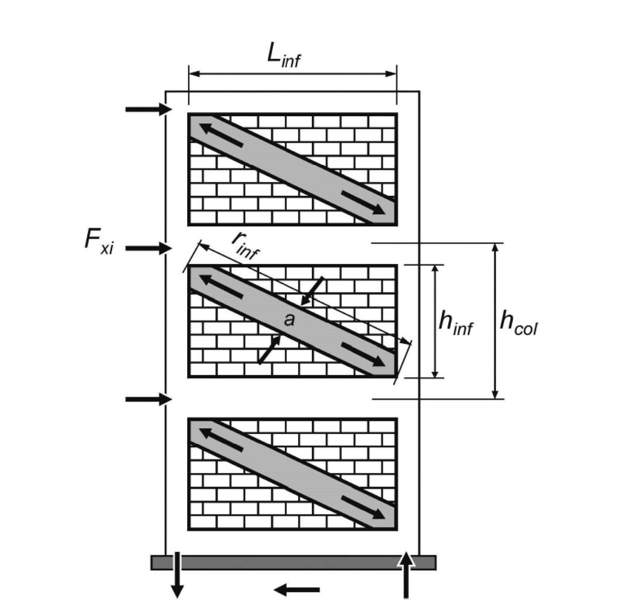
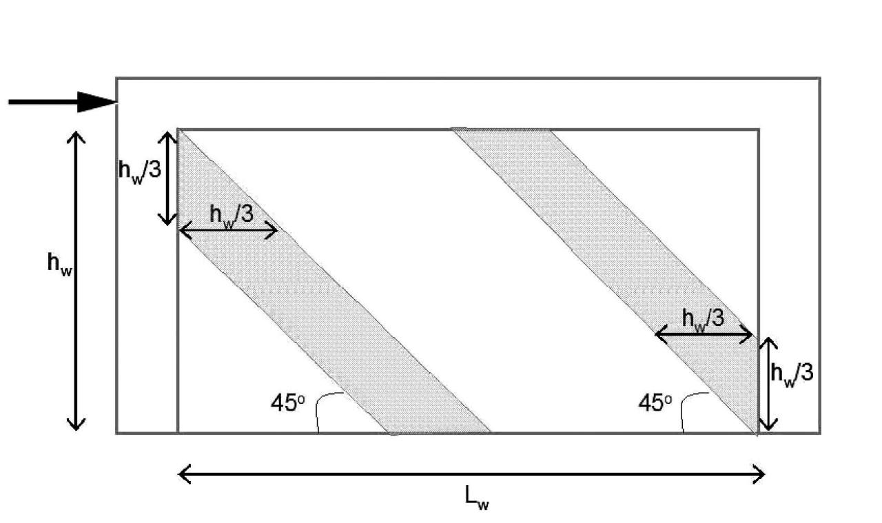
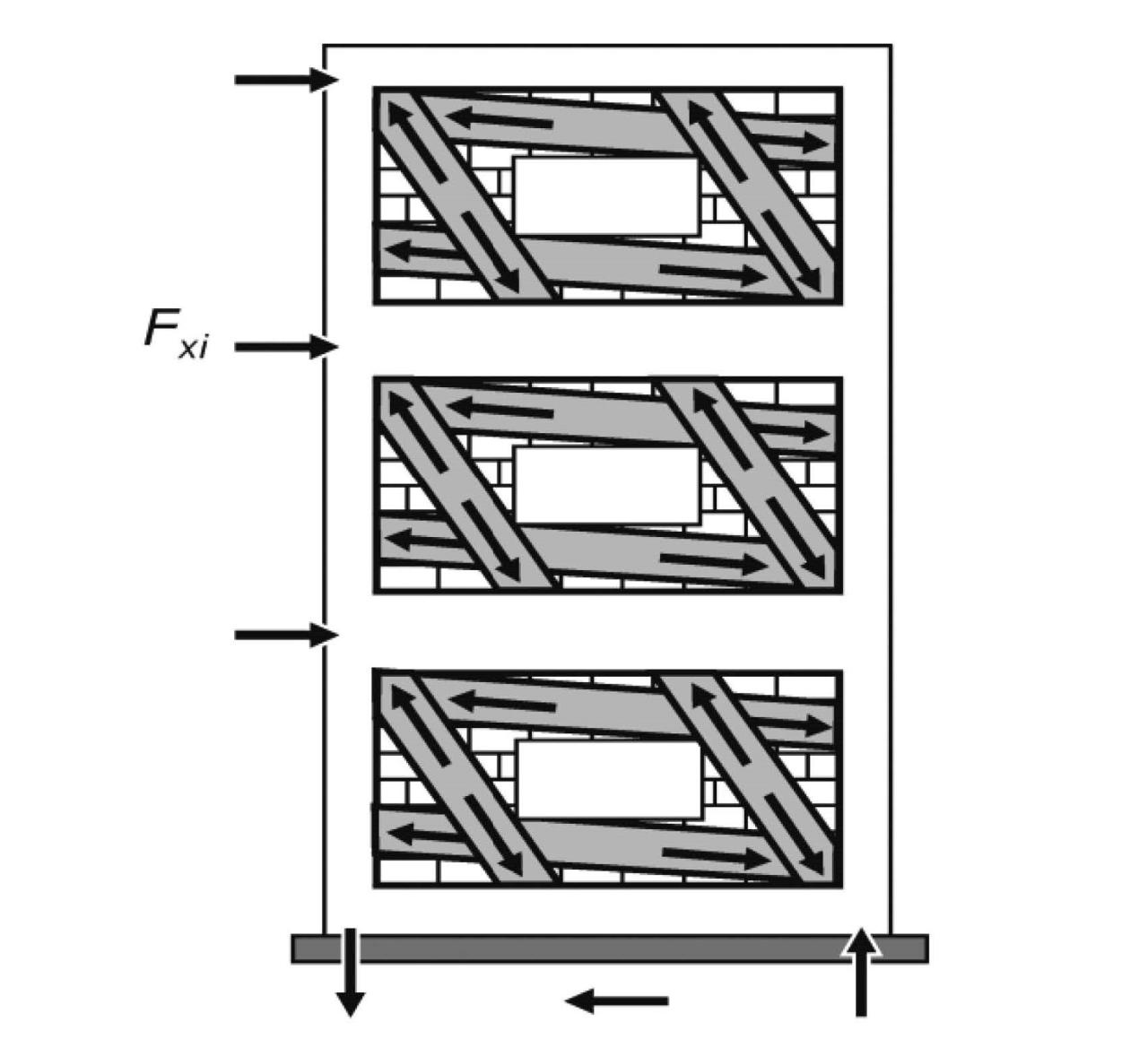
This regular layout can often be difficult to ensure. Architecturally, box-like buildings with few openings are not ideal. Secondly, the local climate may have hot and humid seasons with no HVAC available. Thus, ventilation is key. A possible solution may be to construct all infill walls such that they do not interact with the concrete frame. This again, requires advanced ductile detailing within the frame and special consideration on avoiding out-of-plane failure of the infill. Another possible way to address the need for openings is to keep them outside the diagonals extending from the top corners to the bottom corners of the infill. Keeping windows outside these diagonals will help decrease the overall effect of openings in infills. In the end, close coordination with the architect and creativity is key to solving these issues.
Also keep in mind that as the masonry infill interacts with the concrete frame, it has the potential to cause shear failure in the columns. Adequate shear reinforcement should be provided to mitigate this risk. Remember that when it comes to seismic loading, the additional stiffness the infill provides will cause greater demand on the building when compared to the pure moment frame analysis and hence significant shear demand on the columns occurs.
Because this building method relies on the frame to carry gravity and lateral loads (in conjunction with the infill), a greater amount of detailing is required to ensure that the building has sufficient ductility. Such detailing is possible but requires greater engineering, materials, and labor; something that may be overlooked in the developing world. Often, buildings are built without any engineering. Even if the building is engineered with the proper detailing, if it is too abnormal, the local contractor may find the design unfeasible due to its higher cost. They will then construct the building according to regular practices. So how can we design structures that are seismically safe while being financially viable and culturally appropriate?
For most low to mid rise buildings, confined masonry is a more effective and less costly option that yields reasonable seismic safety. The first known use of confined masonry is in the reconstruction after the 1908 Messina, Italy earthquake and spread throughout the world thereafter. In construction of confined masonry, after a strip footing and plinth beam are laid, the walls are built. Only then do contractors erect the concrete columns and beams around the wall, “confining” it. These are often referred to as tie-columns and tie-beams. In this way, the concrete members and masonry wall work together effectively as a shear wall rather than as separate elements. If possible, the wall should be built in running bond, thus causing the end of the wall to jog in and out from course to course. If this is not done (perhaps for architectural reasons), shear connectors or dowels can be inserted between courses and tied into the concrete column. Both of these will create a better connection between the masonry and concrete, ensuring they act in tandem. Depending on local practice, concrete sill bands and bond beams will be placed below and above openings as well.

Because this system relies on the masonry to carry both gravity and lateral loads, the cross-section of the tie-beams and tie-columns are typically smaller than those of properly designed concrete frame with infill buildings. Additionally, the amount of reinforcement required (both size and number of stirrups) is not as great. Moreover, skilled labor to lay out the proper rebar detailing required in concrete frame with infill construction is crucial. This skilled labor adds more cost and may not even be locally available. These three factors lead to confined masonry typically being the more cost effective building method.
There are a number of methods that have been developed to provide guidance on the design of confined masonry. Three helpful resources are the Design and Construction Guidelines for Confined Masonry Housing, Seismic Design for Low Rise Confined Masonry Buildings, and Design Guidelines for Confined Masonry Buildings. All provide general detailing requirements as well as guidance on material selection and typical sizes. Additional design guidelines and analysis models can be obtained through the library of research papers found online at the Confined Masonry Network’s website.
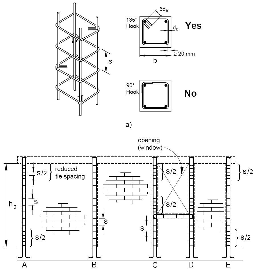
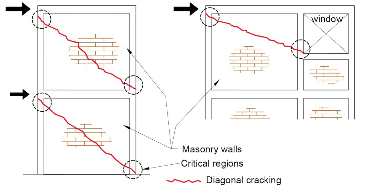
Although confined masonry may inherently provide a better system, it isn’t always the best option. In some of the developing world, concrete frame with infill has performed adequately and is the preferred building technique. This is usually the case where better detailing techniques are in place and the engineering disciplines more strongly grounded. The decision on which method to use will depend on the local practices and expertise, the natural hazards present, the skill of the contractor and other factors that may come into play.

This article by no means serves as an exhaustive discussion on the performance of either of these building methods. Rather, it is meant to bring to light these widely used construction techniques, highlighting the key differences and design resources available. As we approach developing world design with this knowledge, ready to keep learning, we can help create safe, cost-effective, culturally appropriate schools, homes and hospitals.
The EMI Fund
The EMI Fund supports all that we do at EMI. With a strong foundation, we can keep designing a world of hope.
EMI Tech is looking for contributors – write to editor@emiworld.org with your topic and article outline.
