
A look at the most commonly EMI recommended wastewater treatment: soil absorption systems.
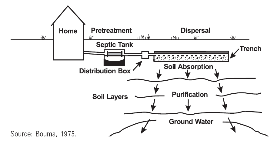
Many EMI projects are built in remote areas where sewers and centralized wastewater treatment systems are not available. Most facilities rely upon on-site wastewater disposal systems. Such systems include preliminary treatment, usually consisting of septic tanks and/or grease traps, and a soil absorption system where the pretreated wastewater is applied to the soil for final treatment and disposal. Figure 1 shows a typical septic system.
When a site is not suitable for a soil absorption system, wastewater treatment can occur in engineered treatment units such as wastewater stabilization ponds, artificial wetlands, or mechanized wastewater treatment systems. These types of systems are more complicated to operate and often require dependable electrical supplies and treatment chemicals. Therefore, EMI usually prefers to recommend septic systems and soil absorption for most of their projects.
A septic tank is a simple below-ground structure that is designed to allow heavy solids to sink to the bottom and oil and grease to float to the surface. Sludge, oil and grease are stored in the tank for eventual removal and disposal. The liquid then passes through the tanks and onto the absorption system. The absorption system is where most of the treatment occurs and is the heart of the on-site wastewater disposal system.
An absorption system functions similarly to a conventional biological wastewater treatment facility. Within the absorption system, bacteria grow on the gravel and soil surface, removing wastewater contaminants that serve as food for the bacteria. At the upper soil surface, where wastewater first encounters the soil, a bacterial film is created. This biofilm is rich in many different bacterial species and other microorganism. Most soluble organic compounds and insoluble particulates, including pathogens, are removed by this biofilm layer.
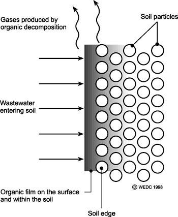
One of the most important factors effecting the proper disposal of wastewater is the thickness of this biofilm layer. If it is too thick, it can interfere with downward movement of wastewater into underlying soil. Too thin and wastewater is not adequately treated. The thickness of this layer depends on many factors including the characteristics of the wastewater; however, the most important factor is the amount of oxygen that is present in the treatment zone. When adequate oxygen is present, aerobic bacteria (which take in oxygen and organic material, and release carbon dioxide) prevail. Under aerobic conditions many multicellular microorganism also thrive, which improves the function of this layer. When there is not sufficient oxygen, anaerobic bacteria (who take in carbon dioxide and organics, and release methane) predominate. Anaerobic bacteria have metabolic rates much slower than aerobic bacteria, resulting in a thick, highly stable biofilm layer that can damage the system’s ability to absorb wastewater.
Types of Absorption Systems
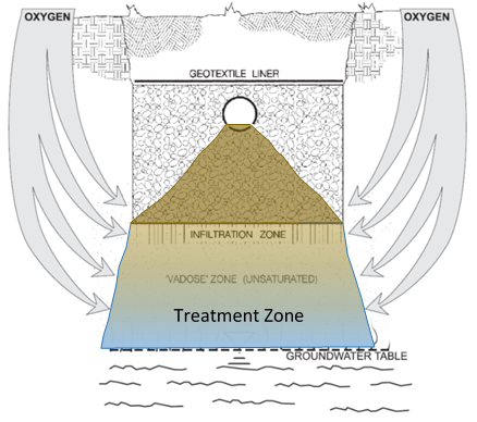
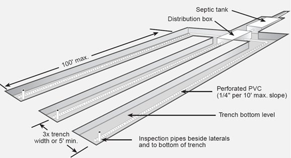
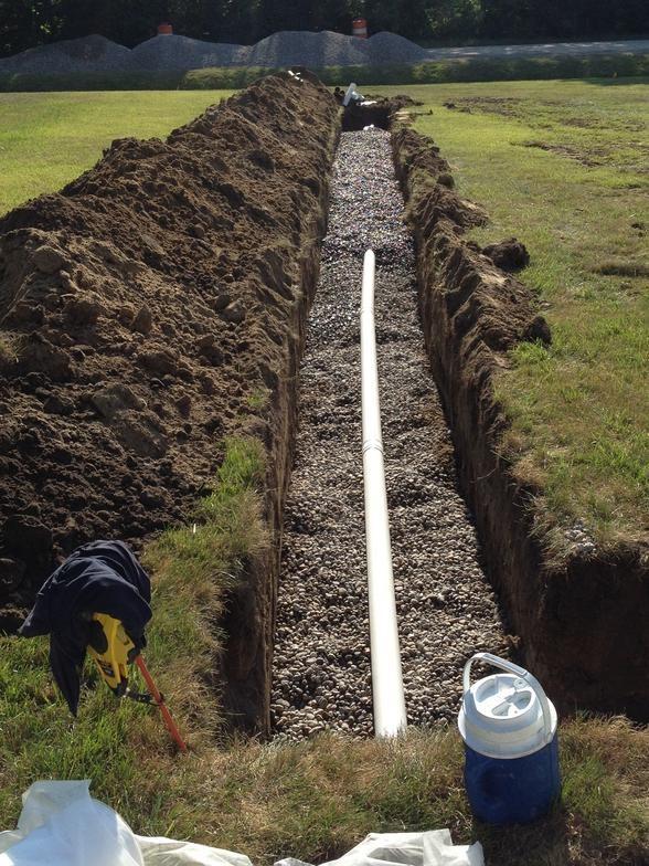
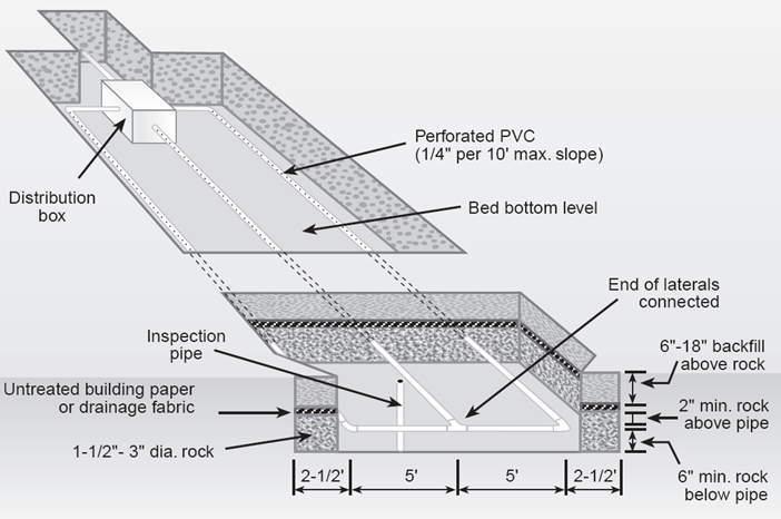
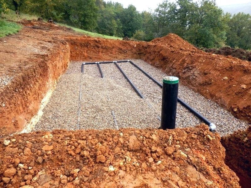
The absorption system consists of a distribution pipe network, a gravel bed under the distribution pipes, and the natural soil. Absorption systems can be arranged in many different configurations to suite the conditions of a specific site. All configurations require at least 1m of unsaturated soil below the treatment zone to adequately treat wastewater. The primary goal of all configurations is to distribute the wastewater evenly across the soil surface and to ensure adequate contact between the soil, wastewater, and atmospheric oxygen.
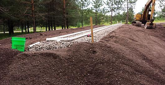
The most common and most effective configuration is a series of parallel trenches with undisturbed soil regions between the trenches, as shown in Figure 5. This configuration maximizes contact between the treatment zone and atmospheric oxygen, improving the treatment process; however, it also requires the greatest land area of the various options.
Alternatively, the absorptive area can be arranged into a single contiguous area, in which case it is termed an absorption field. Eliminating the undisturbed sections of soil reduces the overall size, but decreases the treatment efficiency.
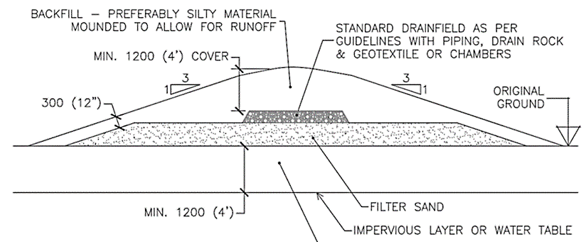
If an adequate thickness of suitable unsaturated natural soil (>1m) does not exist, the absorption system can be built above the natural ground surface, in a mound system. Suitable porous soil or fine sand is imported to provide the needed soil treatment depth. Such systems often require pumping wastewater up to the mound from the below-ground septic tank.
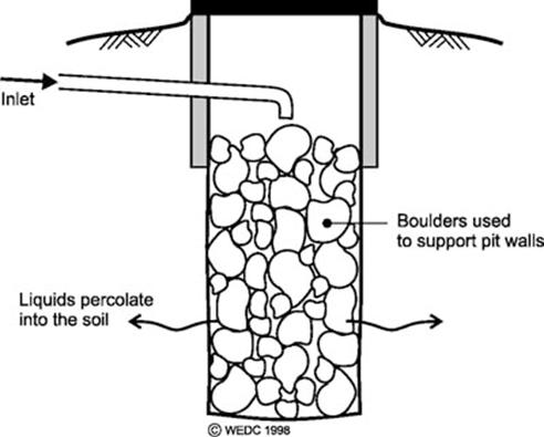
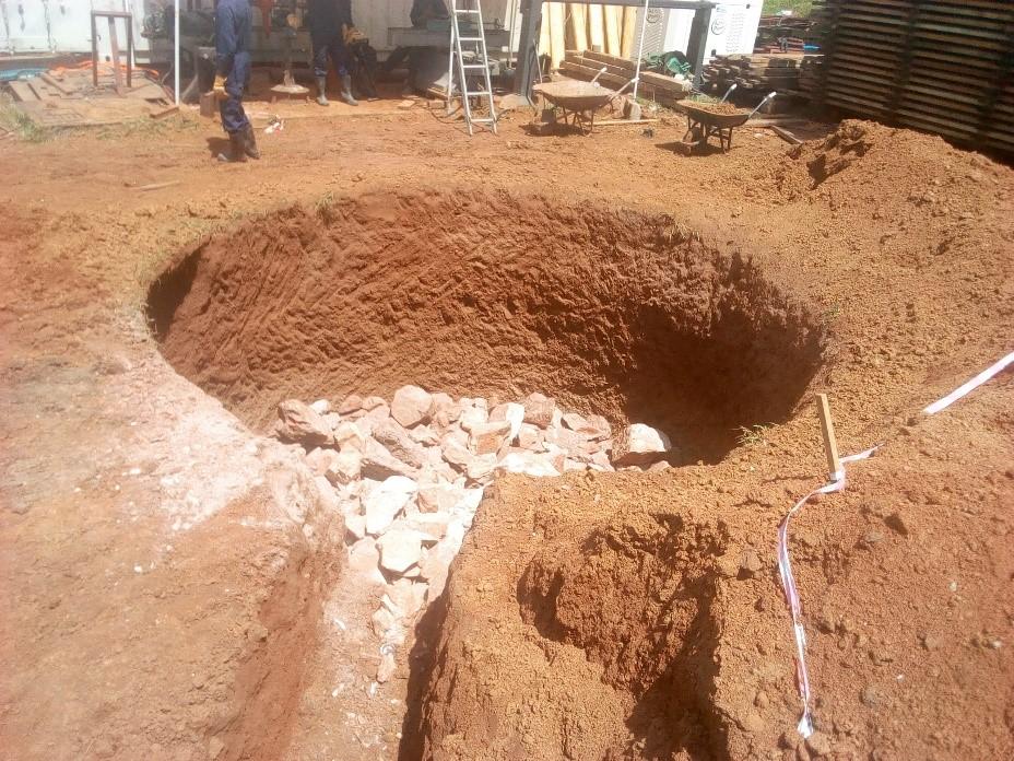
As long as the groundwater depth is greater than 4-5m throughout the year, utilizing a leach pit is another option. Leach pits, also known as seepage pits, are commonly used in developing countries because they are less costly and use the smallest amount of piping and land area. However, because they are usually much deeper than the other options (preventing oxygen from reaching the infiltration surface) they do not treat the wastewater as effectively and can become plugged easily. As a result, they can contaminate groundwater. Most western countries no longer allow seepage pits for on-site wastewater disposal.
Sizing of Absorption Systems
Due to the complexity of the various processes occurring within an absorption system and the multiple factors that affect these processes, selecting the proper size is a difficult undertaking. Absorption systems are usually sized based on empirical relationships between long term wastewater application rates (LTAR) and soil properties. Development of such relationships begun in the 1920s in the USA. Other such relationships are used by different regulatory bodies, but all are based on observations of well-functioning systems.
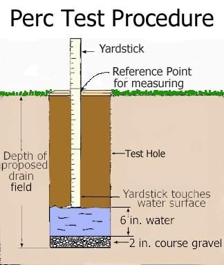
Two types of LTAR/soil property relationships exist. The oldest relationships relate LTAR values to percolation test results. The percolation test was developed to measure soil properties important to absorption system design. Almost every EMI project trip involves performing a percolation test at one or more locations. It involves drilling or digging a hole of a prescribed size and depth, filling the hole with water, and measuring the rate at which water is absorbed into the surrounding soil in units of minutes per inch. No standard test protocol has ever been developed, and several variations of the test are used. The next article in this two-part series will discuss the perc test in more detail.
Many regulatory agencies and other organizations have either adopted the empirical relationship published in 1980 by the USEPA, shown in Table 11, or developed their own similar relationships.
LTAR Table based on percolation rate (Source: USEPA 1980)
|
Soil Texture |
Precolation Rate (Min/in) |
Application Rate (gpd/ft2) |
Application Rate (Lpd/m2) |
|---|---|---|---|
|
Gravel, coarse sand |
<1 |
Not suitable |
Not suitable |
|
Coarse to medium sand |
1-5 |
1.2 |
49 |
|
Fine sand, loamy sand |
6-15 |
0.8 |
33 |
|
Sandy loam, loam |
16-30 |
0.6 |
24 |
|
Loam, porous silt loam |
31-60 |
0.45 |
18 |
|
Silty clay loan, clay loam |
61-120v |
0.2 |
8 |
The second and most recent type of LTAR/soil property relationship is based solely on soil properties. In 2002 the USEPA adapted an approach that determines the LTAR value based only on soil properties. These properties include soil texture (ratio of sand, slit, and clay) and the structure of the undisturbed, in-situ soil column. Many US state regulators have followed suite and now utilize soil properties for sizing absorption systems.

In addition to perc tests or soil characteristics, many other factors must be considered for the proper design of absorption systems. The site assessment should identify a location for the system that will not flood, be an adequate distance from water supply wells and pipelines, as well as buildings and property lines, and have vehicle access for system maintenance. The seasonally high groundwater table (SHGT) should also be identified to ensure there is always 1 meter or more of unsaturated soil present under the system.
The proper design of septic tanks and absorption systems is a critical element of most EMI designs. As such, it is critical to collect adequate information during a site visit in order to properly size these elements.
Related articles

Your investment in EMI is a catalyst for change.
Community transformation starts with design. And design needs a strong foundation. Your donation to the EMI Fund supports everything we do.
EMI Tech is looking for contributors – write to editor@emiworld.org with your topic and article outline.